
With passenger rail vehicles in particular, a wide range of engines and cars have to be inspected in increasingly shorter intervals to determine the extent to which the wheel axles are suffering from wear and tear. The numerous external components on the rail vehicles, such as the transmission, brakes and wheel disks, make it impossible to externally inspect the different types of axles with nondestructive ultrasonic methods. On the other hand, most of today‘s axles are formed with longitudinal bores, which permits internal inspections. Of primary interest here is the detection of forming or already formed longitudinal and transverse cracks on the surface of the axle, in addition to defect volume. Hollow axles were originally “insonificated“ by hand. This involved taking a sensor that matched the bore diameter and inserting it into the axle with a push rod. The tester had to ensure that the probe was rotated evenly, while simultaneously keeping an eye on the ultrasonic echoes output by the measurement instrument, so that the entire contour of the axle could be examined for defects. Growing test volumes make this manual process too time consuming and costly.
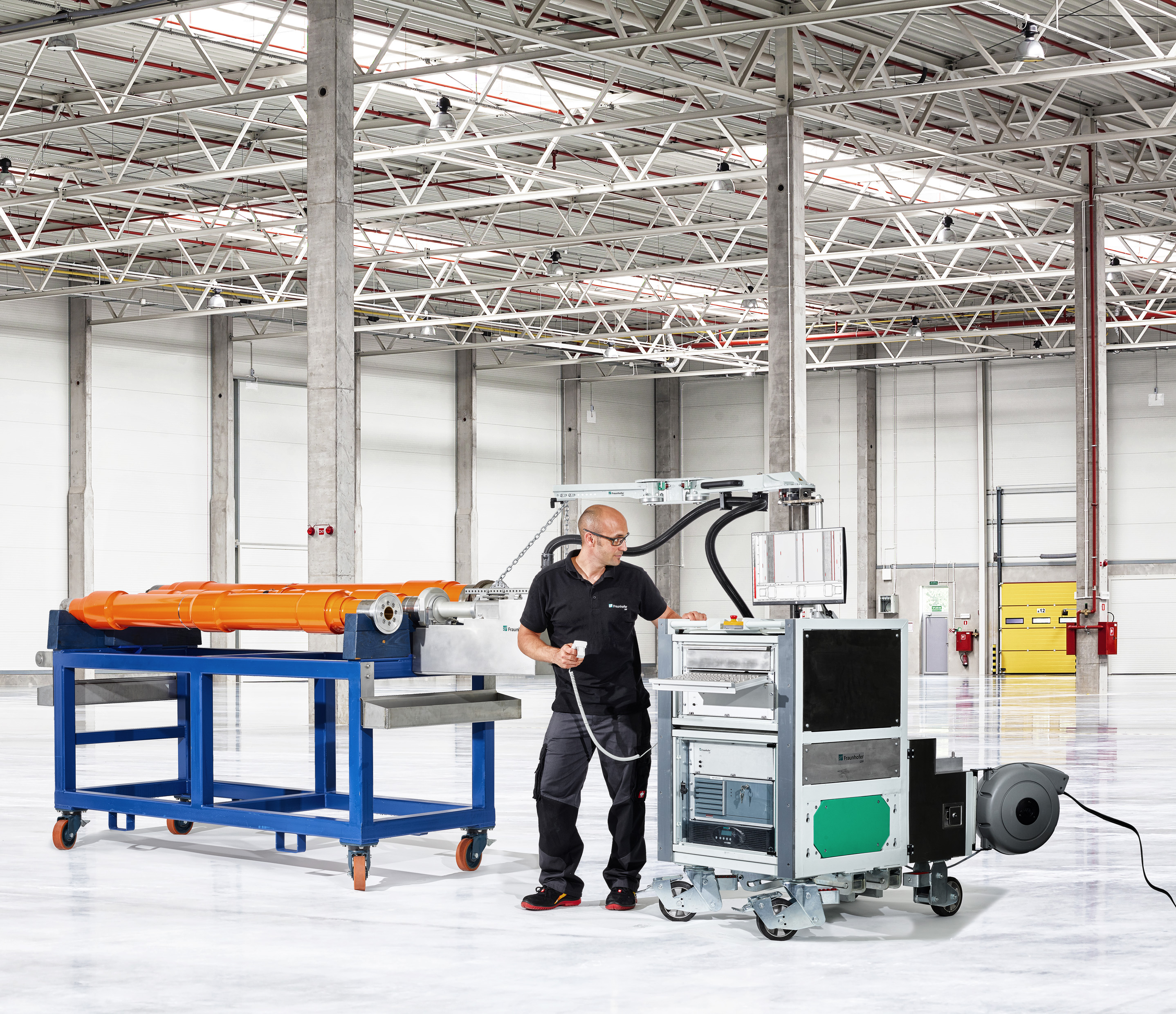
To ensure greater throughput and shorter rail vehicle idle times, Fraunhofer IZFP developed an automated ultrasonic hollow axles inspection system.
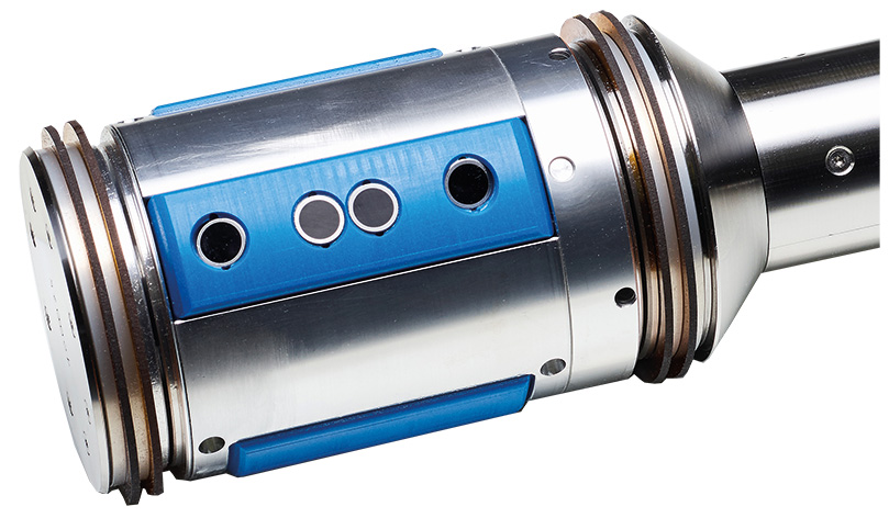
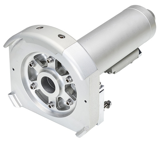
Axles with longitudinal bores are inspected with ultrasonic test technology, using oil as a coupling medium. The system relies on immersion technique probes mounted on a rotating sensor platform. Various beam angles are used to detect transverse, longitudinal and volume defects. Using an adapter, the sensors installed on the feeder unit can be docked to any type of axle. After starting the test, the sensor platform is fed to the other side of the axle with a chain while the sealed area of the probe is flooded with oil.
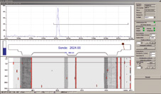
The measurement data, which are recorded as the chain is pulled back, can be immediately observed on the display. The probes run along a helix path across the longitudinal bore. After the measurement is completed, areas of interest can be analyzed in more detail, after which the results are recorded and stored.
Application
- Heavy maintenance
- Operational maintenance
Technical features
- Test trolley dimensions (L×W×H) in [mm]: min. 1060×720×1210 / max. 1060×720×2008
- Feeder unit with integrated cable and chain spool, easy sensor attachment
- Remote control operated electric hoist for docking the feeder unit
- Test PC with keyboard, 19-inch display
- Ultrasound electronics with position-dependent amplification
- PLC control
- Easy-to-use test software
- Simple parameter configuration
- Simple measurement results documentation
- Manual and automatic measurement modes
- Special analysis mode
- PGC editor for configuring new axles
- Option to save the TD data for offline analysis
- Integrated 10-liter oil tank providing constant pressure
- 230V UPS for changing locations without shutting down the system, 30-minute buffering
- 4.5 MHz measurement probe
- 30 mm sensor with a total of four probes (2 × 37° and 2 × 0.5°)
- Sensors for 53 mm and 90 mm bores, each with a total of eight probes (2 × 37°, 2 × 0.5°, 2 × 45° and 2 × 70°)
- Adaptable to other sensor dimensions
- Rotation speed: max. 90 rpm, feeder: 3 – 5 mm per rotation
- Pulse gap 1°
 Fraunhofer Institute for Nondestructive Testing IZFP


